
Power and environment
Keeps every host fed through a blip, is built to land the fleet in order if an outage outlasts the batteries, and watches the room.
4 UPS at 240 V · 6,395 W measured · 103% rack 2 failover load
What this layer is for #
Every other layer assumes it has power and a room cool enough to run in. This layer makes that assumption safe. It feeds every host through a blip, it is built to land the fleet in an ordered way if an outage outlasts the batteries, and it watches the two rooms the site lives in. The ordered shutdown is configured and tested in parts; that the whole fleet finishes inside the battery window has not been verified, as the state on the day records. That is accepted until a planned whole-site outage allows the rehearsal.
Power and cooling are one system, sized off one set of numbers. The hardware’s own features come first, a UPS return delay or outlet sequencing in preference to logic written on the hosts, because a setting held on the UPS card still applies to a host that will not boot. On Node0 cooling is judged off the same output-watt figures this layer already polls.
How it is built #
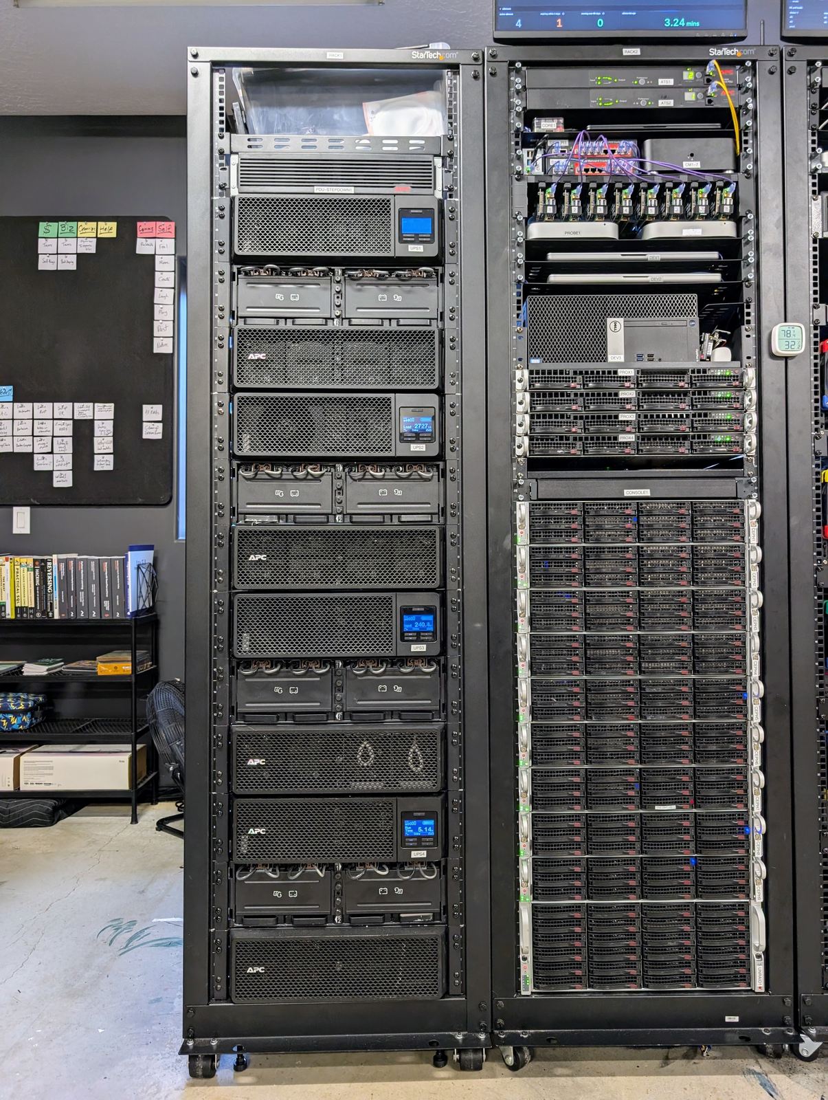
Node0 occupies two basement rooms: a network room with a small rack and its own portable air conditioner, and a server room holding three 42U racks. Rack 1 is the dedicated power rack, feeding racks 2 and 3 over an A/B dual path. Every rack is dual fed and so is every host, either by two power supplies straddling both sides or by a transfer switch in front of a single-supply box.
The drawing traces that path once, from the panel to the racks.
| device group | role | form | rack | firmware or OS |
|---|---|---|---|---|
| ups1 to ups4 | one UPS per rack side, 4,800 W nameplate, at 240 V | APC SRT 5000 plus two external battery packs each | 1 | APC network management card |
| ats1 to ats9 | A/B source selection, in hardware | APC AP7723, 1U | 2 (two), 3 (seven) | APC AOS, mixed versions |
| four metered strips | infeed metering, one A and one B per rack | ServerTech Sentry3 CDU | 2, 3 | firmware 7.1f, end of life |
| env1 | environment hub | Raspberry Pi 4B on a shelf | 2 | Debian 13, Home Assistant in Docker |
The transfer switches. An ATS is a box that picks between an A feed and a B feed in hardware, so a host with one power supply still looks dual fed. All nine were reachable on 20260920. One carries newer firmware, upgraded to fix a dead management link. Their management sits on an isolated management VLAN with per-card access control, and lesson 5.8 carries the credential lesson from it.
The metered strips. They read infeed totals only, with no per-outlet wattage, which is why per-host power comes from the servers’ management controllers instead. Each strip also polls its own feeding UPS over SNMP as a stock feature.
Two shutdown servers. core1 and core2 both run NUT, Network UPS Tools, polling all four UPS network cards over SNMPv3 with authentication and encryption. Every host watches both, one for each of its feeds. On 20260920 core1 counted 41 clients on each rack 2 unit and 18 on each rack 3 unit. Since 20260913 both servers hold a tagged leg on the management VLAN, so commands to the UPS cards never travel through the firewalls. The low-battery setting reads 900 seconds on all four units, so the 20260904 change is in force on the hardware and not only in the runbook.
One environment hub. env1 has been live since 20260902. The
rework of 20260912 inverted the design. Prometheus became the single
timeline and Home Assistant the sensor and actuator hub only, because
the telemetry the project meant to log had already arrived in Prometheus on
its own. Eleven sensor devices report through it: thermostat, temperature,
smoke, leak and contact sensors across the two rooms. The network room’s
rack also has three UPS units of its own, two of them a NUT primary for one
firewall each, watched for notification only.
The measured load. On 20260921 the four units put out 6,395 W between them, read live from core1 and from Prometheus, against a combined rating of 19,200 W. Rack 2’s pair draws 4,928 W and rack 3’s pair draws 1,467 W. The strips read 6,984 W of infeed, about 9% above the UPS output. Lesson 5.20 recorded the two meters 5 to 6% apart in the other direction and set a band on the ratio; the 20260921 reading sits outside that band, which is exactly the departure the lesson says to look into, and it is open.
The rooms. On 20260921 the rack inlet read 25.9 C, the hot aisle 32.7 C and the network room 27.0 C, against an 80 F setpoint.
The decisions #
20260824: all four UPS units standardised at 240 V #
Workload. Four UPS units feeding two racks through transfer switches.
Requirement. A transfer switch must agree with its sources about which one is healthy.
Choice. Run all four at 240 V rather than leave two at 208 V.
Accepted trade-off. A pass over every unit, and a re-check of each downstream device’s input expectations.
Verified. The transfer switch parked off its preferred source returned to it, and the source-health false negative the mismatch was causing stopped (20260824).
20260904: fifteen minutes of low battery, and one sequence for the storage tier #
Workload. Around 59 hosts on six platforms, including a Ceph cluster, the Proxmox cluster in front of it, and a storage array with a slow stop.
Requirement. An ordered shutdown that finishes before the batteries do. No host may shut itself down quietly while its neighbours keep writing to a cluster it is part of.
Choice. Raise the low-battery threshold on the UPS cards from the two-minute default to fifteen minutes, and make that single event the only trigger rather than an early-warning scheme with thresholds of its own. Take the Ceph and Proxmox tier down and bring it back as one orchestrated unit, never node by node.
Accepted trade-off. The fleet reacts later in an event than a tiered design would, and the tier returns slowly through a single sequence that has to be right. An unwanted shutdown cost more at the time than a slow reaction, because power return did not yet exist.
Verified. The tier tested empty on 20260904, 114 seconds down and 1,295 seconds back up. The threshold read 900 seconds on all four units on 20260921.
20260909: rack 2 at 103% of one UPS, accepted rather than fixed #
Workload. Rack 2, fed by a pair of UPS units, one per side.
Requirement. Decide whether that pair must survive losing one of its two units.
Choice. Accept that it cannot. Rack 2’s pair draws 4,928 W and one unit is rated 4,800 W, so the pair is 102.7% of a single unit, recorded as 103%. A lost partner puts the survivor over its rating. The figure is a recording rule, watched rather than remembered, and silenced as a known state.
Accepted trade-off. Protection exists only while both units in a pair are up. Rebalancing onto rack 3 was rejected. Rack 3’s pair draws 1,467 W, or 31% of one unit, and that headroom is reserved for GPU hardware not yet installed.
Verified. Measured again at 4,928 W on 20260921.
What it cost #
Replacement costs are not yet researched, and purchase prices are not published. The layer’s hardware is seven UPS units, four large and three small, eight battery packs, nine transfer switches, four metered strips, eleven sensor devices and one hub.
What broke #
- Lesson 5.5 , The whole fleet had two minutes to shut down a 218-terabyte array. The default low-battery window gave the fleet two minutes; one setting on the UPS cards fixed more than a redesign would have.
- Lesson 5.10 , 103% of a UPS, and the nameplate number that was wrong for months. The failover budget was computed against a capacity figure lower than the hardware’s own, and the correction on 20260917 to the real 4,800 W changed what the rack 2 pair means.
- Lesson 5.11 , A UPS shutdown that works perfectly and still leaves the fleet dark forever. A clean shutdown plus a BIOS set to restore its last state gives a fleet that stays off, because the last state it saw was off.
- Lesson 5.13 , Real outages and planned outages need different UPS commands, and rehearsing one triggered a battery scare. Every output return also runs a self-test, which once flapped a battery-pack detection.
- Lesson 5.16 , An interim fix without a new part solved a real heat problem. The server room baselined near 90 F with no active cooling; redirecting an existing branch of the home’s air conditioning holds about 78 F.
State on the day #
Healthy on 20260921: four UPS units at 240 V, polled by both NUT servers over SNMPv3; nine transfer switches reachable; four metered strips reporting infeed; the fifteen-minute threshold live on every unit; eleven sensor devices publishing into Prometheus; the rack inlet at 25.9 C against the 80 F setpoint.
The largest open item is the power-outage rehearsal, because power return is the least proven part of the layer. The BIOS setting that makes a host power on when AC returns was applied to all fourteen Supermicro chassis on 20260913 without a reboot, so it is unproven until each one reboots. Three of the GPU hosts need a physical visit. The UPS commands that turn a mains return into a genuine AC cycle were rehearsed once, unloaded, on a single unit, with Christoph at the panel. Testing power return end to end is on Christoph’s list of what Node0 stable means. It needs a planned whole-site outage; until one is scheduled, the risk is accepted and each part is proven on its own.
Anything that cannot finish inside the fifteen-minute window is also untested against it, most notably the real stop time of the storage array. Cooling rests on one thing, the redirected air conditioning holding 78 to 80 F with no dedicated unit in the room. A 34,000 BTU mini-split was priced on 20260827 and deferred, so the redirected air is the summer ceiling for the site as it stands. A fire is detected and pushed to a phone, with no automated fleet shutdown behind it yet. Rack 3’s headroom is expected to close the way rack 2’s did once the GPU hardware lands. The cooling loop is still at stage one, observe, and nothing adjusts the thermostat automatically, by choice, not yet, until the data supports it.
Source: node0 as-built v0.1, section 3.10. Sanitized: checklist v0.1, 20260921; voice pass 20260921. Capture of 20260921; the private site keeps changing, this page does not. Part of oznog.com/node0.